It was time to upgrade my networking equipment in my homelab. I needed two 24p 1GB switches with 10GB uplinks to facilitate moving my homelab into my crawl space and out of my office. As things are configured right now I’d easily saturate a 1GB uplink between the switches and since I don’t have any 10GB in my homelab yet the CSS326 fits the bill. I am replacing a single first generation Ubiquiti 24p switch with two CSS-326-254G-2S+RM’s.
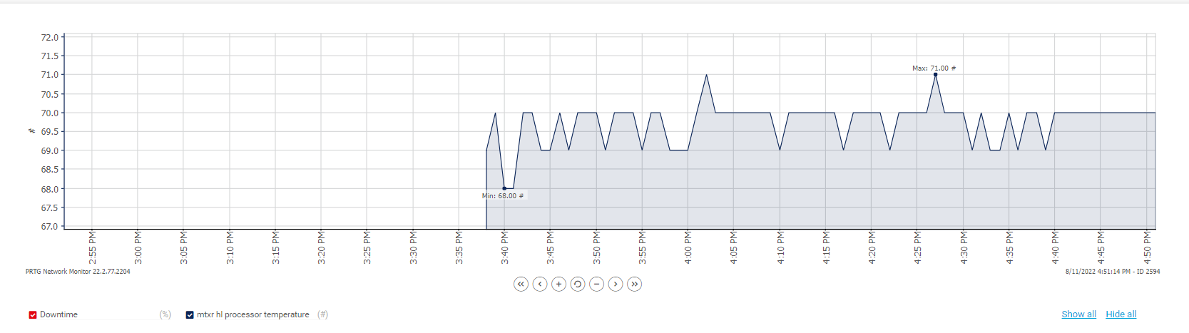
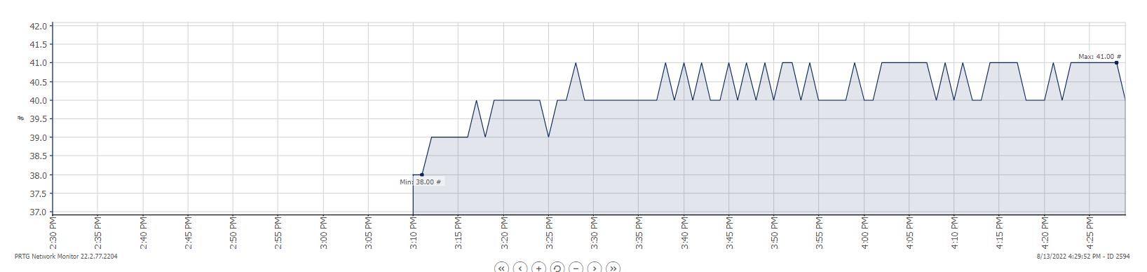
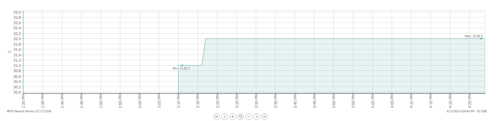
After receiving my CSS-326-254G-2S+RM’s I plugged them in to test them and verify my 10GB SFP+ transceivers were working properly. While I was doing that I also hooked them into PRTG using SNMP so see what kind of monitoring data I could pull from them. I had been optimistic that these new switches would run cooler than my Ubuiqiti but that does not seem to be the case. My Ubiquiti (which has a fan) runs at about 76c. The MikroTik ran at about 70c without a fan. An improvement but not a fantastic one.
Below is 1 hour of monitoring data from the MikroTik with a single 10GB SFP+ installed in it running idle but connected to my Ubiquiti via 1GBe and the other CSS-326 via fiber.

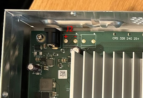
The CSS-326-254G-2S+RM has a mount for a 40mm fan and figured I’d just buy a fan and slap it in there. Unfortunately once I popped it open I saw there was no header to connect a fan to. I did some digging and came across this video which shows a significant temperature improvement once a fan is installed and the creator helpfully pointed out where you could tap into the switches board to get power. I also found this helpful forum post that also showed the J2 header and mentioned which connector was positive (+) and which was negative (-).
“YOU DON’T NEED TO DO THIS. Mine runs in a warm rack enclosure and has for 3 years now”
– Someone I know
Using my multimeter I checked the J2 connector and it outputs 24v a few seconds after the switch boots up. From what I have read, the J2 only outputs power if you connect the included power cable to your CSS-326. If you use PoE to power the CSS-326 the J2 connector does not output any power. I did not test this but since I’m using the supplied power cables this isn’t a problem for me.
Noctua is my preferred fan manufacturer but they do not make a 24v 40mm fan which means I had to use a buck converter to drop 24v down to 12v for the Noctua NF-A4x20 I wanted to use. I will put a full parts list at the bottom of this blog post.
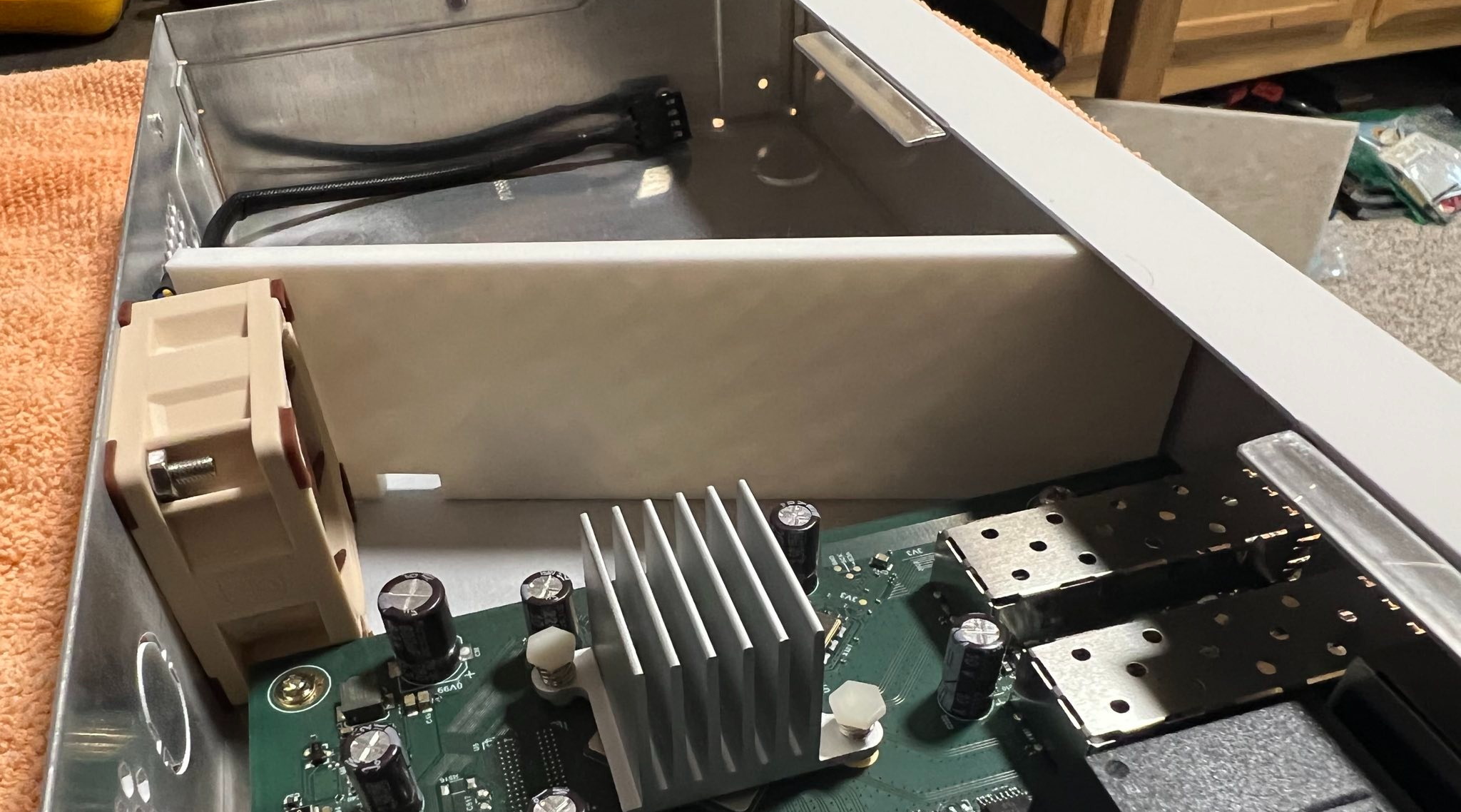
I did not solder to the J2 connector as my first step. I just want to show where it is before continuing. Please excuse my poor soldering skills. This is only my 3rd or 4th time seriously soldering something and my first time soldering to a PCB. Using the information I gathered, I am labelling which connectors I treated as positive (+) and negative (-). I might be wrong but it all worked in the end.

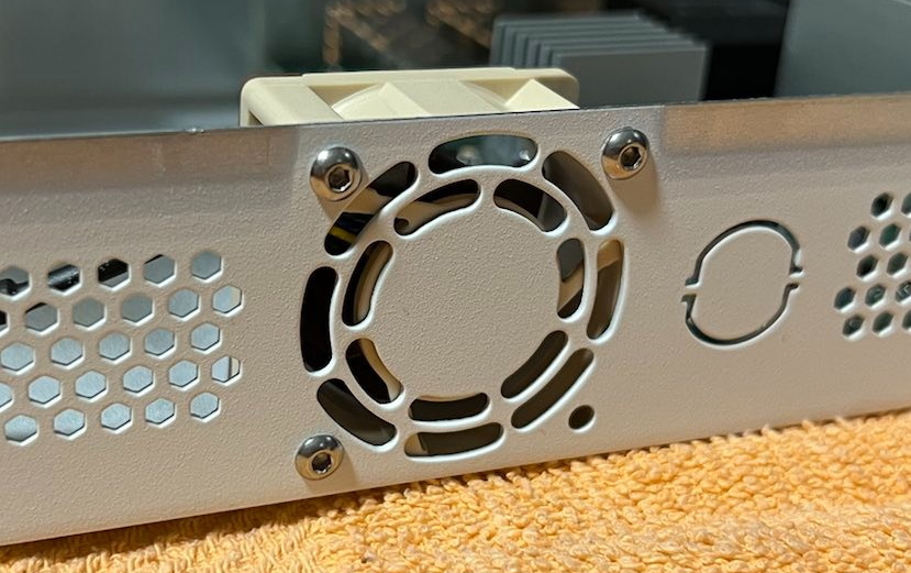
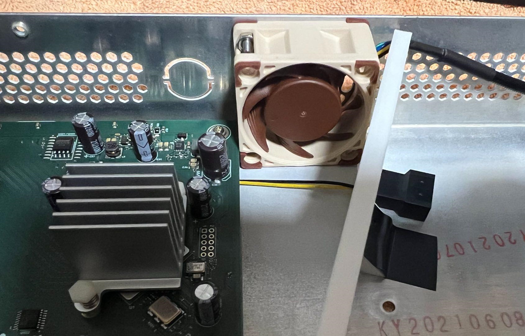
Easy step first, I mounted the fan into the CSS-326 using some M3x12mm screws, nuts and a little patience.
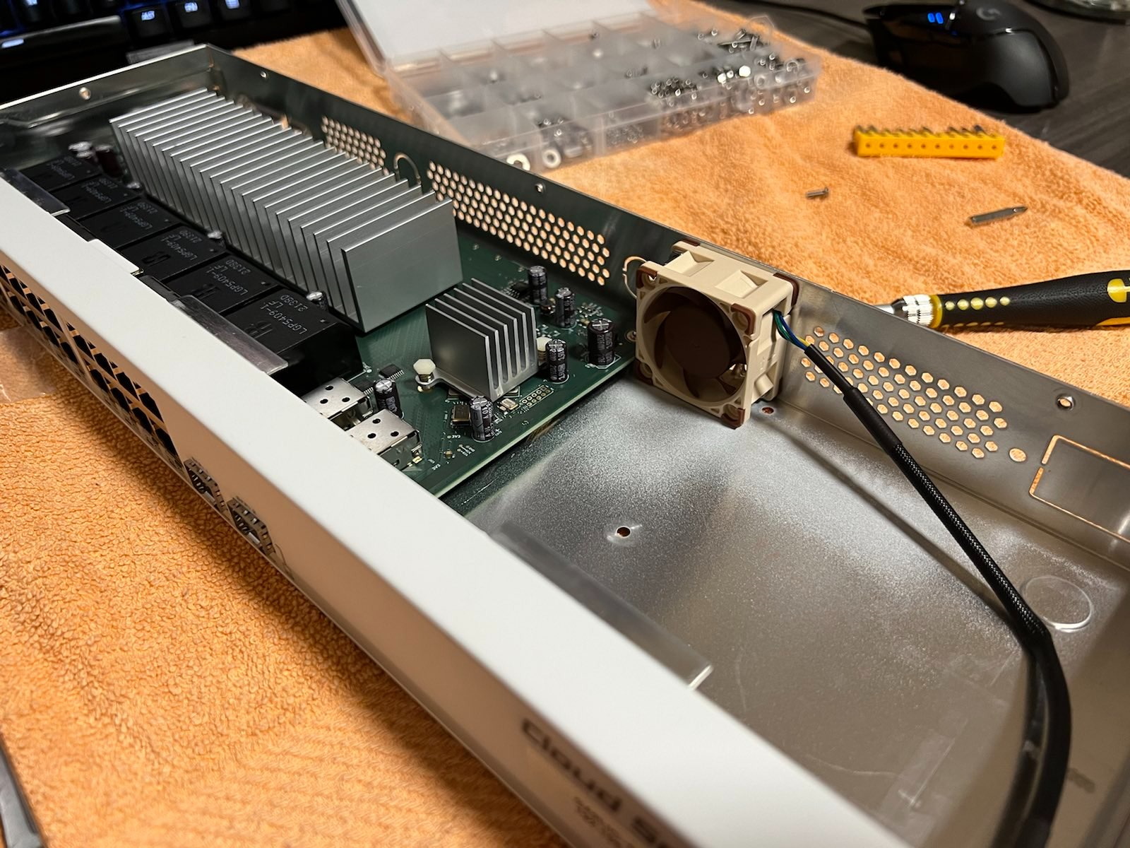
I then 3D printed a baffle to block off the dead space to the right of the fan if you’re looking at the switch from the front. The electrical tape is just to hold the baffle in place while I’m fiddling inside the switch. Once you put the top back on the baffle is firmly pinched in place and won’t move. As designed the baffle is overkill. It could be 3mm thinner but I don’t care about saving 6g of filament so I didn’t change it for the second switch. The STL is linked at the bottom of this post in the parts list.


Using the cables and adapters that came with the Noctua fan I was able to piece things together in a way that I would never need to touch the J2 connector again if something failed. The buck converter can be detached from the main feed connected to the J2 and the fan can be disconnected from the buck converter. If either piece ever dies it should be very simple to replace them. I specifically used the extension cable and the Y-splitter. You can toss the one labelled “Low-Noise Adapter” into your spare parts bin, we won’t be needing it.
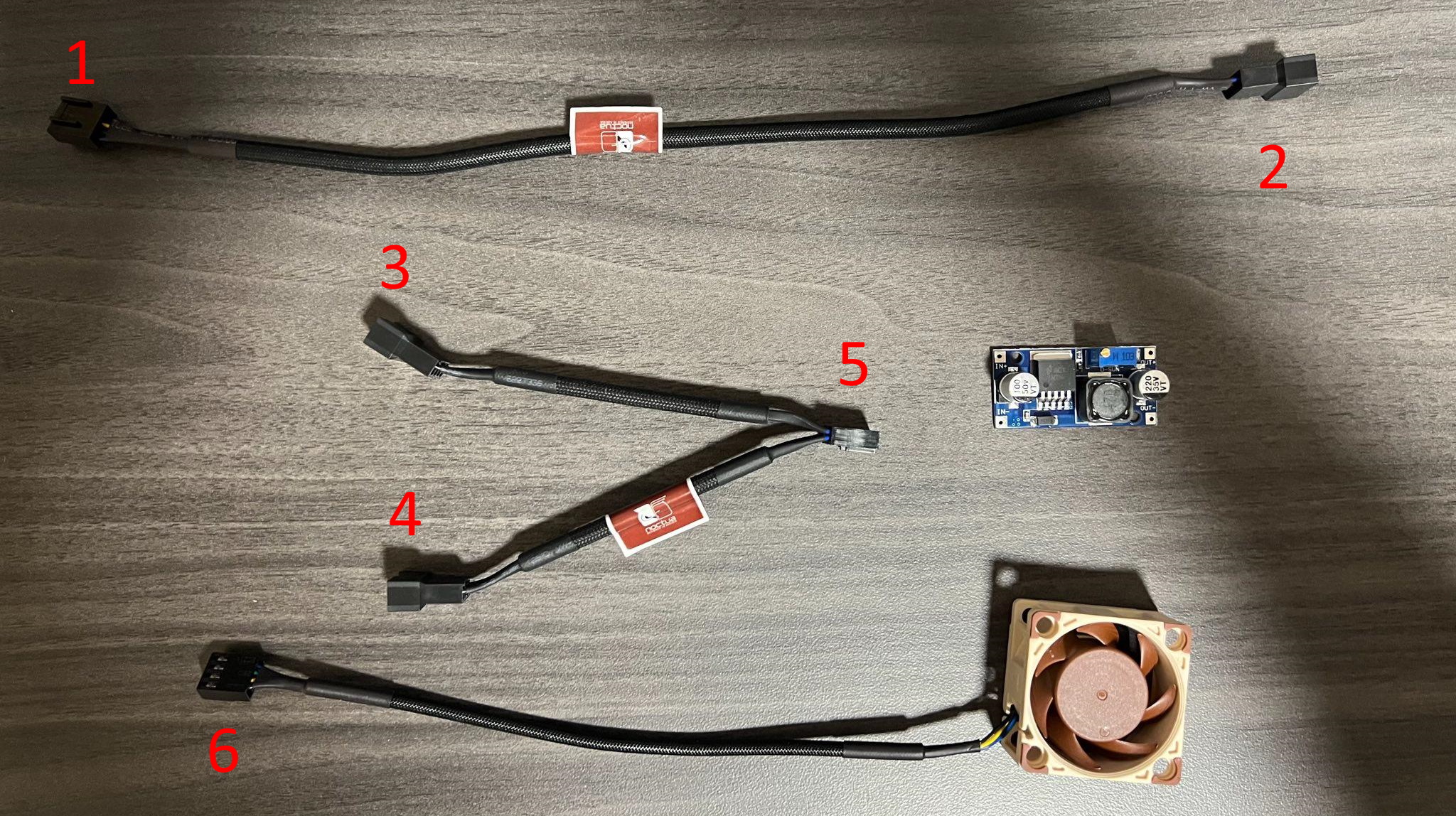
I removed all of the sheathing from the cables, removed any blue/green wires because I only need the yellow and black ones and then cut off some of the connectors.
Piecing them all together they will look like this:
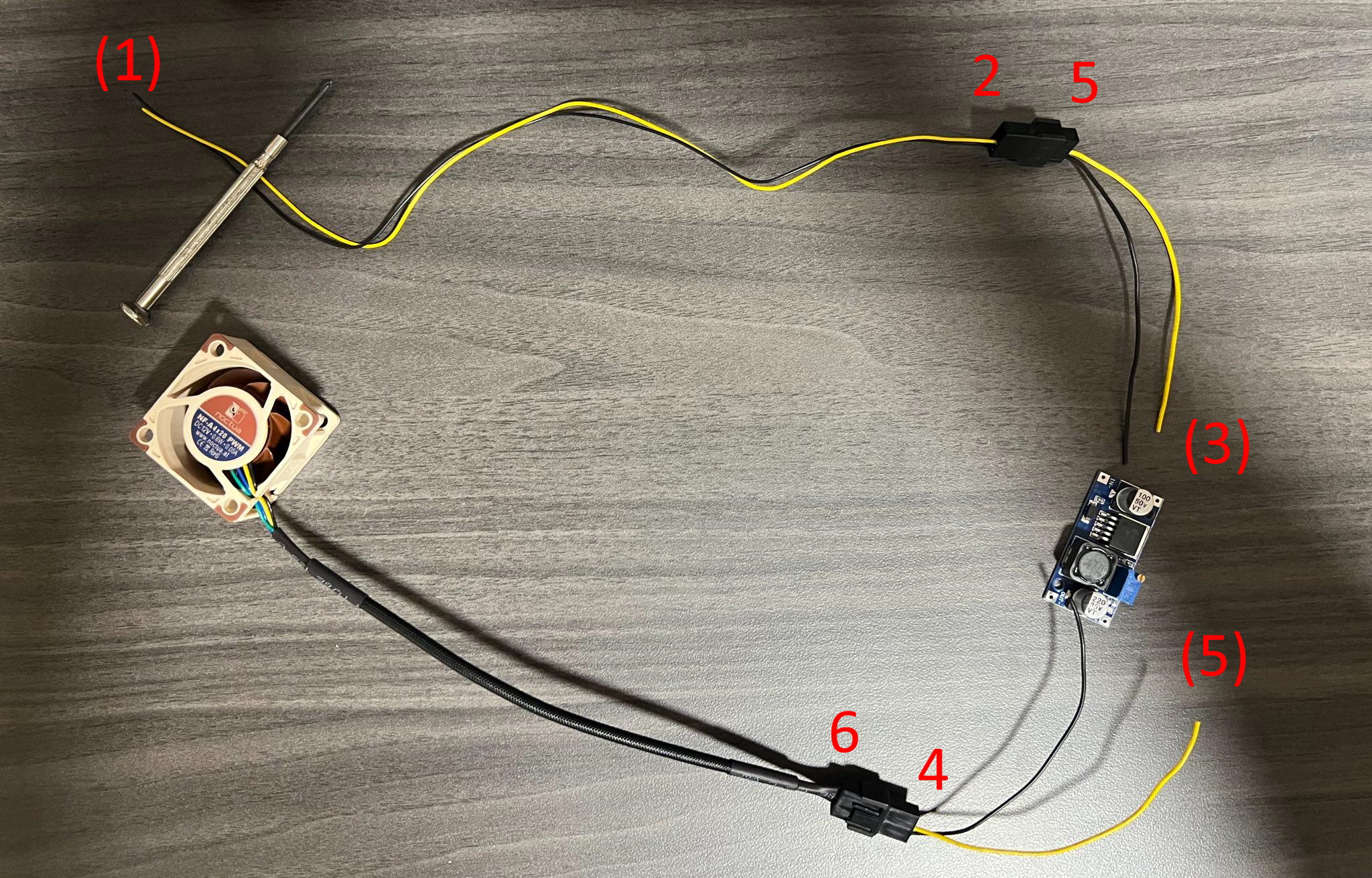
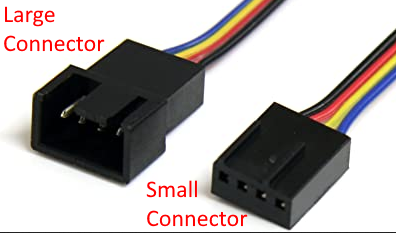
(1) – Is the small connector on the extension cable that gets removed and soldered to J2
2 – Is the large connector on the extension cable that does NOT get removed. The IN on the buck connector will plug into this.
(3) – Is the large connecter on the upper leg of the Y-splitter that gets removed and soldered to the IN on the buck converter
4 – Is the large connector on the lower leg of the Y-splitter that does NOT get removed. The fan will plug into this which is attached to the OUT on the buck connector.
(5) – Is the small connector at the base of the Y-splitter. You want to cut this so that the smaller connector remains attached to the upper leg of the Y-splitter that you removed the large connector (3) from. This then gets soldered to the OUT on the buck converter
6 – Is the fans connector, leave it alone. You will plug it into 4 when everything is done
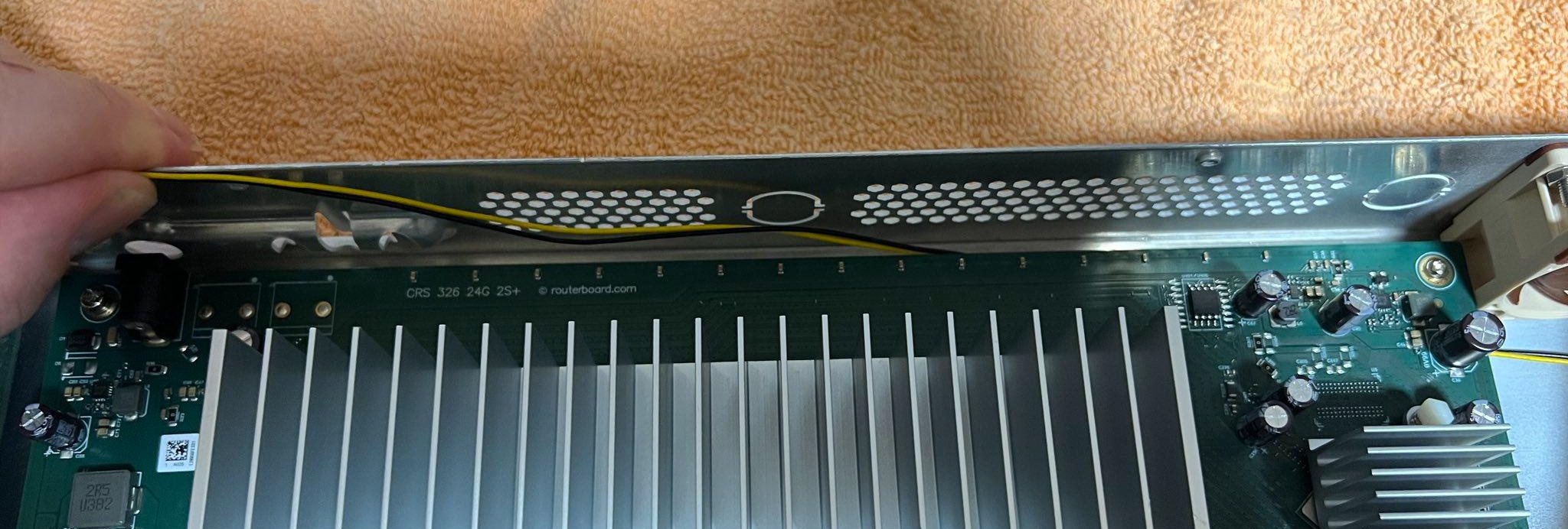
Before soldering (1) to the J2 connector feed it through the gap in baffle and under the mainboard so you can keep it all tucked out of the way. If you don’t do this first you’ll have to remove the mainboard and baffle to do it later. There should be just enough wire to make it to the J2.
Solder it all together based on the diagram above and plug everything in except for the fan. We need to adjust the buck converter before we can plugin the fan. Odds are its default setting is too high (more than 12v) for our Noctua.
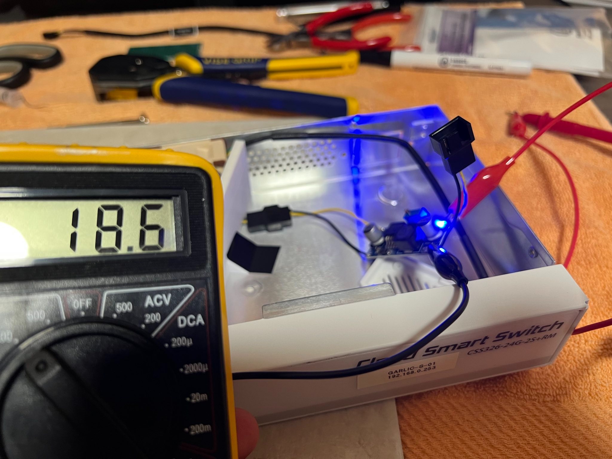
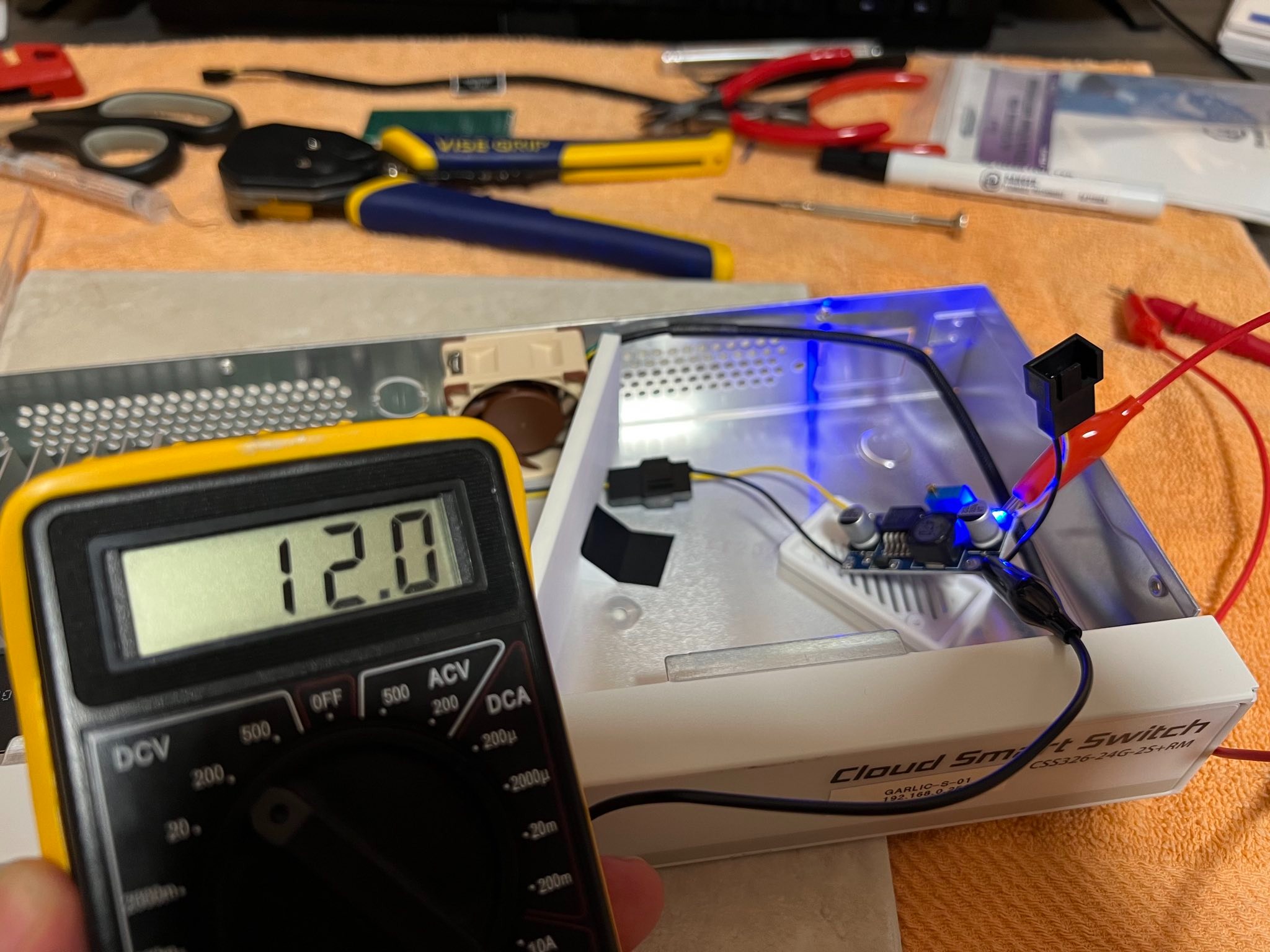
Set your multimeter for DCV at whatever setting can read higher than 20v, connect alligator clips to the OUT side of the buck converter and then connect those to your multimeter. Plug the power into the switch and check your multimeter reading. Using a flathead screw driver carefully turn the small knob on top of the blue box on the buck converter until your multimeter reads 12v.
Disconnect the power from the switch, remove your multimeter and alligator clips, screw together the buck converter case and put the top back on the CSS-326. You’re done!
My final results were that the switch ended up running about 30c cooler and the SFP was 11c cooler.
I get MikroTik saving cost by not including a fan in the switch but I really wish they would have at least installed a connector on the J2 to make adding a fan an easy option.
Update – 2022-08-20
I moved my entire homelab off my old Ubiquiti switch yesterday and have some real word temperatures with actual load on the switch:
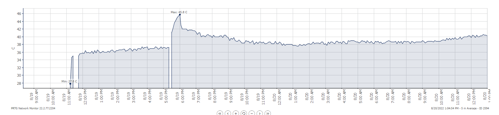
The first low section on the left was the switch idling with no load while I configured VLANs and LAGs. The gap is me unplugging it, sliding it under my Ubiquiti switch and powering it back on. The initial high temperature (45.8c) was from the Ubiquiti smothering it while I did cable swaps. I eventually removed the Ubiquiti switch and the temperatures dropped a bit.
Parts List
Buck Converter – I used a “LM2596 DC-DC Buck Converter Step Down Module Power Supply DIP Output 1.25V-30V 3A”. There are a ton of these on Amazon. Here is a non-referral link to a 10pack I bought.
Noctua NF-A4x20 – Since there is plenty of room in the case I went with the 40mm * 20mm version of this fan to get the most air movement possible.
Buck Converter Case – I printed one of these to insulate the buck converter from the chassis of the switch.
Baffle – Completely optional but I designed and printed one of these to block off the section of the case to the right of the fan mount. Seemed pointless to circulate that air since there are no electronics in there except the buck converter.
Thank you for the perfectly timed article! I’ve recently gotten into the Mirkotik universe with a Hex S and am loving it – the feature set and real-time statistics are just mind blowing at this price point. I’m just contemplating replacing my HP 1810-24G switch & Hex S with a CRS326-24G-2S+RM (and maybe a 10Gbe SFP or two) which would handle both switching and routing duties. I’ve also got many things cooled with silent Noctua Fans, so my first question was “I wonder if I could get a 40mm Noctua in there”? :-)
Glad it’s helpful. I ended up putting the low noise cable into the Mikrotik I have in my office. I found the Noctua made a bit too much noise for me. My switch was at ear level though and now that it’s under a table it might not be a big deal but I’m not opening it back up to find out.
Just an FYI, the CSS326 support DC input range of 10-30v with max of 19w on MikroTik product page. So if you have 12V DC adapter around. Usually I have plenty lying around after shucking USB drive anyway and I think usually is 12V DC 1.5A so it’s perfect. And if you swapping out the DC adapter from 24V to 12V, then there is no need for buck converter. Also the link to the Noctua fan you use is 4-pin PWM fan and in this setup it won’t be use all 4 pins and only two pins are in-use so 2 or 3 pin 40mm fan will be ok also. Have been doing it this way for almost a year now w/o any trouble.
it would be cool to print a casing that would precisely take in air in one place, pull it through all the radiators and bring it directly to the fan
This is a good idea honestly. I didn’t think of making something that elaborate but it could easily be done. I’d also like to cut a hole and use a 140mm fan to cool the whole thing. I can hear the Noctua in the switch I have in my office, not annoying but louder than I would like.
something like this, only tighter) https://cdn.nag.ru/pimcore.public.static/thumbnail/%D0%9D%D0%BE%D0%BC%D0%B5%D0%BD%D0%BA%D0%BB%D0%B0%D1%82%D1%83%D1%80%D0%B0/%D0%A2%D0%BE%D0%B2%D0%B0%D1%80%D1%8B/MCP-310-29003-1N/23019/image-thumb__23019__1920x1920/8e26dd22d1de9afc2df20ec45c716832ea9f77dca7943ab59260b21c1fdab46b.webp
FYI for those reading this in 2025, Noctua now has a 24v fan. The NF-A4x10. Soldering will still be required since the J2 is just pads with no connector but you won’t need to buck converter any more. I just ordered one and will come back to report how it works when installed.
Appears the specific model is “NF-A4x10 24V PWM”: https://noctua.at/en/nf-a4x10-24v-pwm
Ok I have installed the NF-A4x10 24V PWM now and it worked perfectly soldered directly to the J2. No voltage converters required. I didn’t print and install the baffle and just pushed the wire from the fan under the main board without even removing the mainboard from the case. it’s JUST long enough with the 4 pin to to 2 wire connecter that is included to reach the J2. I’m seeing a drop from an average temp of 73C to 55C under 55% cpu load. Longest and most difficult part of the process was remembering how to turn on my pinecil soldering iron as I haven’t need to use it in a while.